10+ entity flow diagram
It was developed to reflect more precisely the properties and constraints that are found in more complex databases such as in. When it comes to simple data flow diagram examples context one has the top place.

Dbms Case Study Dbms Erd Management Information Systems
Event Creator Entity Relationship Diagram.

. Customer Journey Mapping 18 See All Basic Customer Journey Map Template. Double-click on an entity process or data store and then click and hold one of the orange circles and drag the line to the appropriate symbol. Such a diagram would illustrate the object-oriented view of a system.
Biasanya DFD banyak digunakan oleh seseorang yang bekerja di bidang sistem informasi. A message can flow in any direction. In the case of a more complicated system the totality of several objects as a rule processes is united and represented on the diagram in the form of one object.
Add data flow to the DFD. The labels of processes can be verb phrases. From left to right right to left.
Data Flow Diagram Levels. You can use it as a flowchart maker network diagram software to create UML online as an ER diagram tool to design database schema to build BPMN online as a circuit diagram maker and more. Economics business accounting and related fields often distinguish between quantities that are stocks and those that are flowsThese differ in their units of measurementA stock is measured at one specific time and represents a quantity existing at that point in time say December 31 2004 which may have accumulated in the past.
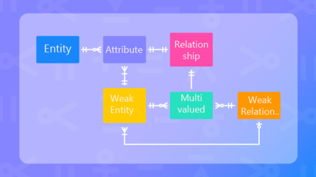
Context data flow diagram. Hingga saat ini DFD banyak digunakan dalam pengembangan. All diagrams display particular symbols according to their uses.
Where use cases are used to represent the set of activities services that the system needs to perform and actors are the entity that works under defined roles within the system. Data Field Entity Relationship Diagram. When it comes to system construction a class diagram is the most widely used diagram.
Drawio can import vsdx Gliffy and Lucidchart files. The object orientation of a system is indicated by a class diagram. A lifeline with an entity element represents system data.
It is often used as the basis for data flow diagrams or DFDs as they are commonly known. UML use case diagram is one of the types of UML diagram which is used to represent the dynamic diagram by mapping the structure of the systems using actors and use cases. Flowchart Maker and Online Diagram Software.
The entity can access all the databases and it also controls the operations of the Manager. A context diagram is a top level also known as Level 0 data flow diagram. Data flow diagram DFD adalah ilustrasi alur sebuah sistem.
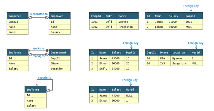
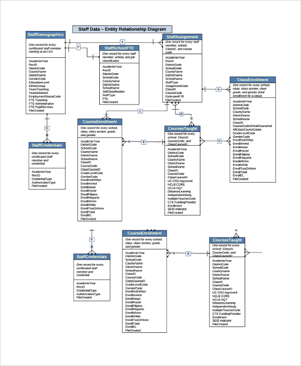
Point of Sales POS System. The ER Diagram show the relationship between entities tables and the primary key-foreign key relationships between the tables relationships. Symbols used in Context Diagram.
At the top of the symbols column youll see a large letter T. Otherwise it means youre allowing an external entity access to your data files and stores. External Entity- an element in the system diagram that inputs data into the information system and retrieves processed data.
They help to identify different system elements and their relationships with each other. The Level-2 Data Flow Diagram of an Online Banking System is as follows. The Bank can modify or eliminate any policies as well as create new policies for the Online Banking System.
Add a title and share your data flow diagram. An entity is a thing person or. Data stores are displayed by nouns.
Definition and example with explanation. Entity relationship diagrams in software engineering. Click it and drag it to where you want to add a title.
Data Flow Diagram should not involve more than 10 objects excluding arrows representing data flows. External entities are objects outside the system with which the system communicates. Order Purchase Entity Relationship Diagram.
A flow variable is measured over an interval of. This complicated compound object is presented in the form of a separate flow. UML Class Diagrams is a type of static structure diagram that is used for general conceptual modeling of the systematics of the application.
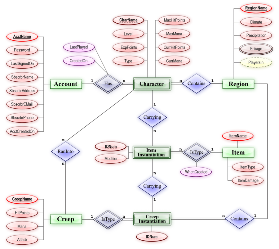
An Entity Relationship ER Diagram is a type of flowchart that illustrates how entities such as people objects or concepts relate to each other within a system. It acts as an entity that controls all the branches of the Bank. Movie Studio Entity Relationship Diagram.
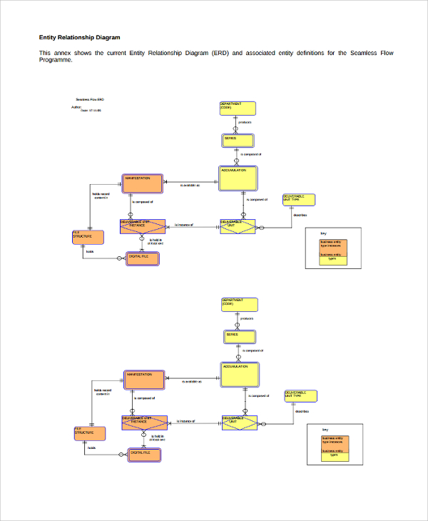
Entity relationship diagrams are used in software engineering during the planning stages of the software project. External entities are sources and destinations of the systems inputs and outputs. Entity-relationship modeling or ER Diagram symbols are part of a conceptual approach to design that models objects as abstract data types and the relations between these objects as predicates.
ER Diagrams are most often used to design or debug relational databases in the fields of software engineering business information systems education and research. For example in a customer service application the Customer entity would manage all data related to a customer. Diagram ini dipopulerkan oleh Ed Yourdon dan Larry Constantine pada akhir 1970-an dalam bukunya yang bertajuk Structured Design.
An arrow from the Message Caller to the Message Receiver specifies a message in a sequence diagram. The enhanced entityrelationship EER model or extended entityrelationship model in computer science is a high-level or conceptual data model incorporating extensions to the original entityrelationship ER model used in the design of databases. Read along as we show the symbols when developing a system with a context diagram and their functions.
Entity Relationship Model Wikiwand

10 Erd I E Entity Relationship Diagrams Interview Q As Java Interview Questions Big Data Interview Questions
What Is An Er Diagram And How To Implement It Edureka

Er Diagram Of The Current Common Iq Meta Model Entities Boxes With Download Scientific Diagram
39 Handy Info Ideas Relationship Diagram Database Design Diagram Design
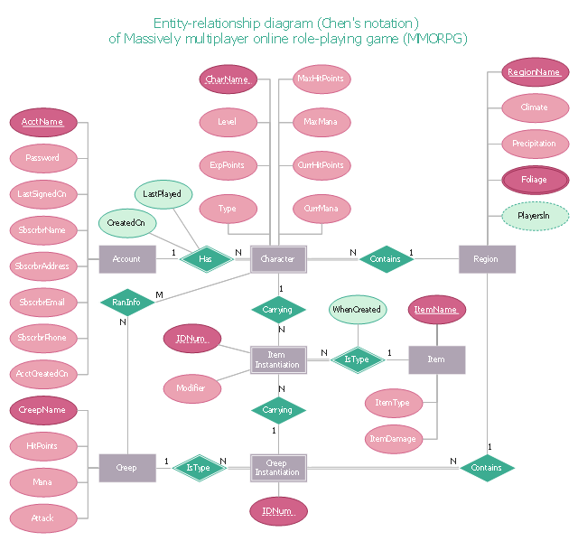
Chen S Erd Of Mmorpg Android Gui Examples Of Flowcharts Org Charts And More Erd For Online Multi Player Game
How Do You Draw A Visual Paradigm Entity Relationship Diagram
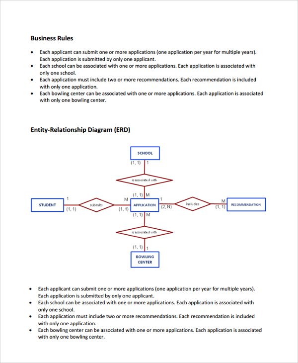
Free 7 Sample Relationship Diagram In Pdf Ms Word

Software Diagram Examples And Templates Network Diagram Examples Technical Flow Chart Example Diagram Examples

Free 7 Sample Relationship Diagram In Pdf Ms Word

Database Flowchart Symbols Flow Chart Symbols Basic Flowchart Symbols And Meaning Database Flowchart Symbols
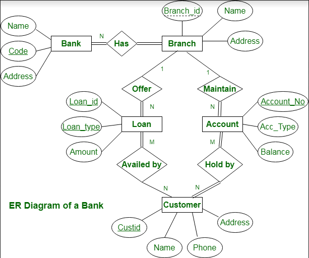
Er Diagram Of Bank Management System Geeksforgeeks

Introduction To Er Diagram Model Knoldus Blogs

Local Area Network Lan Computer And Network Examples Software Diagram Examples And Templates Personal Area Pan Networks Computer And Network Examples Example Of Diagram
Free 7 Sample Relationship Diagram In Pdf Ms Word
Free 7 Sample Relationship Diagram In Pdf Ms Word

Invoice Data Model Erd Database Design Data Modeling Business Architecture